CamCal 007 Camera Calibration
Digital Image Processing using OpenCV (Python & C++)
Highlights: In this post, we will explain the main idea behind Camera Calibration. We will do this by going through code, which will be explained in details.
Tutorial Overview:
Intro
In a last few posts, we have talked about modeling a projection, perspective projection, camera translation and rotation and all of this stuff will be of a great importance for you in order to understand this post. So, if you missed that, jump back and prepare for programming.

Basically the main idea of camera calibration is to find parameters that would help us to solve some problems, which we will be doing here. Things that can be done using these parameters are distortion correction, object size measurement in the real world, which we will be talking more about in later posts.
These parameters are intrinsic parameters, distortion parameters, rotation and translation vectors.
1. Setup
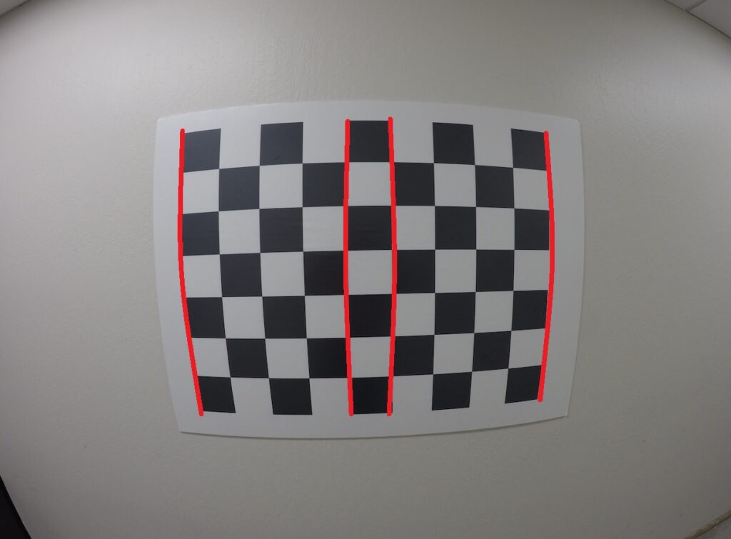
You have probably seen the pattern from the last picture, that pattern is used a lot for calibration. Beside that, there is also similar one with circles. But we will use this one for now. So basically cheap cameras produces a lot of distortion. Let us first clear what is distortion. It is just the alteration of the original shape. So straight line will appear curved. This is also known as radial distortion. We want to minimize this effect.
From the last post, we seen that our camera matrix looks like this:
$$ M= \begin{bmatrix}fx & s &{x}’_{c} \\ 0 & fy &{y}’_{c} \\0 & 0 & 1\end{bmatrix} \begin{bmatrix}1 & 0 & 0 &0 \\0 & 1 &0 & 0\\ 0& 0 & 1 &0\end{bmatrix}\begin{bmatrix}R_{3\times 3} & 0_{3\times 1}\\0_{1\times 3} & 1\end{bmatrix}\begin{bmatrix}I_{3\times 3} & T_{3\times 1}\\0_{1\times 3}&1\end{bmatrix}$$
Where \(fx\) and \(fy\) are focal length, and \({x}’_{c}\) and \( {y}’_{c}\) are offsets. And we also had a translation and rotation matrices:
$$ R = \begin{bmatrix}R_{3\times 3} & 0_{3\times 1}\\0_{1\times 3} & 1\end{bmatrix}$$ $$ t = \begin{bmatrix}I_{3\times 3} & T_{3\times 1}\\0_{1\times 3}&1\end{bmatrix}$$
So the basic idea is to calculate extrinsic and intrinsic parameters and then, to calibrate the camera. In short, the extrinsic parameters represents a rigid transformation from 3D world coordinate to 3D camera’s coordinate and the intrinsic parameters represents a projective transformation from 3D camera’s coordinate into 3D image coordinates.
Fundamentally at the heart of calibration is this idea of having some points whose three dimensional location in the world we know, and that we identify them in an image. And then we have to compute some sort of a mapping from a scene to the image. One thing we can do is we can actually put an object in the scene, like pattern shown before. So clearly, given enough points in the world and the image, we should be able to calibrate, recover the calibration matrix. To finish this section, we need to find corners on shown pattern, and connect them.
2. Finding Corners
In order to find these corners, we can use the method shown before, Harris Corner Detector and then we can sort of do some type of filtering, where we get rid of detection along edges of the image, and only keep ones in the middle. But there is no need for this, we are working with OpenCV and there is provided function for that, both in Python and C++. This function is called findChessboardCorners. There is also similar function for detecting circles, if we choose that type of calibration.
First thing we need is a good database of images. And there are a few good ones. The first is provided by Udacity and can be downloaded from their GitHub, and the second one is provided by a Computatonal Vision group at Caltech.
Python
C++
#include <opencv2/opencv.hpp>
#include <iostream>

using namespace cv;
using namespace std;

int main()
{
    int numBoards = 36;
    int numCornersHor = 8;
    int numCornersVer = 6;
    int numSquares = numCornersHor * numCornersVer;
    Size chessboardDimensions = Size(numCornersHor, numCornersVer);

    Mat image, gray;
    Mat drawToImage;
    Mat cameraMatrix = Mat::eye(3, 3, CV_64F);
    Mat distortionCoefficients;
    vector<Mat> rvecs;
    vector<Mat> tvecs;
    vector<Mat> savedImages;

    vector<vector<Point3f>> object_points;
    vector<vector<Point2f>> image_points;

    // This creates a list of coordinates (0,0,0), (0,1,0), (0,2,0)...(1,4,0)... so on
    vector<Point3f> obj;
    for(int j=0;j<numSquares;j++)
        obj.push_back(Point3f(j/numCornersHor, j%numCornersHor, 0.0f));

    String imagepath = "GO*.jpg";
    vector<String> filenames;
    cv::glob(imagepath, filenames);

    for(size_t k=0; k<filenames.size(); k++)
    {
        // Read the image
        Mat image = imread(filenames[k]);
        // Convert it to a grayscale
        cv::cvtColor(image, gray, CV_BGR2GRAY);

        vector<Point2f> corners;
        bool found = false;
        found = findChessboardCorners(image, chessboardDimensions, corners, CV_CALIB_CB_ADAPTIVE_THRESH | CV_CALIB_CB_NORMALIZE_IMAGE);
        image.copyTo(drawToImage);


        if(found){
            cornerSubPix(gray, corners, Size(11, 11), Size(-1, -1), TermCriteria(CV_TERMCRIT_EPS | CV_TERMCRIT_ITER, 30, 0.1));
            drawChessboardCorners(drawToImage, chessboardDimensions, corners, found);
            cout << "Corners detected" << endl;
            //cv::imshow("Corners", drawToImage);
            //cv::waitKey(0);

            image_points.push_back(corners);
            object_points.push_back(obj);
        } else {
            cout << "Original image" << endl;
            //*cv::imshow("Original image", image);
            //cv::waitKey(0);
        }

        Mat temp;
        drawToImage.copyTo(temp);
        savedImages.push_back(temp);
    }
What we get with this code is shown on the next picture.

3. Calibration
Once we have all of these coordinates in real world and in the image, we can use that to calibrate the camera. OpenCV function for that is calibrateCamera and we will pass objpoints and imgpoints which represents points in 3D space and in the 2D image plane respectively. It will calculate mean projection error, intrinsic parameters, distortion parameters and translation and rotation vectors.
Python
C++
cameraMatrix.ptr<float>(0)[0] = 1;
cameraMatrix.ptr<float>(1)[1] = 1;

calibrateCamera(object_points, image_points, Size(1280,960), cameraMatrix, distortionCoefficients, rvecs, tvecs);
4. Undistortion
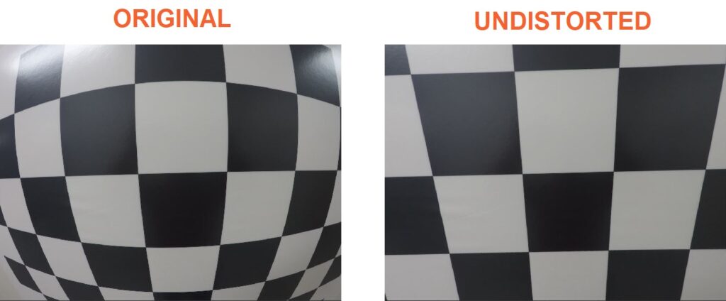
Next thing we can do when we have all of these parameters is to fix a distortion problem. Distortion is solved using these equations:
$$ x_{corrected} = x(1+k_{1}r^{2}+k_{2}r^{4}+k_{3}r^{6}) $$
$$ y_{corrected} = y(1+k_{1}r^{2}+k_{2}r^{4}+k_{3}r^{6}) $$
And for tangential distortion:
$$ x_{corrected} = x + [2p_{1}xy + p_{2}(r^{2}+2x^{2})] $$
$$ y_{corrected} = y+ [p_{1}(r^{2}+2y^{2})+2p_{2}xy] $$
Where \( (k_{1} k_{2} p_{1} p_{2} k_{3}) \) are called distortion coefficients.
Now it is finally time to see the results:
Python
C++
    // Undistortion
    Mat imageUndistorted;
    // Read the image
    image = imread("test_image.jpg");
    undistort(image,imageUndistorted,cameraMatrix,distortionCoefficients);
    cv::imshow("Original", image);
    cv::imshow("Undistorted", imageUndistorted);
    cv::waitKey(0);

    return 0;
}
Summary
After all of theory and math we have finally finished camera calibration. As you can see, we don’t really need a lot of code to this. So to conclude, as long as you have enough pictures to extract feature points, you will have a good calibration. It is recommended that you use more than 20 pictures for this. After this, in the next post you can read more about stereo vision.