CamCal #001 Perspective Projection
Highlights: In this post we will continue an exploration of the projection modeling. The basic modeling equations will be written in the matrix form. New concepts, such as vanishing points and parallel lines in images will be explained.
Tutorial Overview:
- Perspective imaging – matrix equations
- How do parallel lines in 3D world behave in the image?
- What is a vanishing point?
1. Perspective imaging – matrix equations
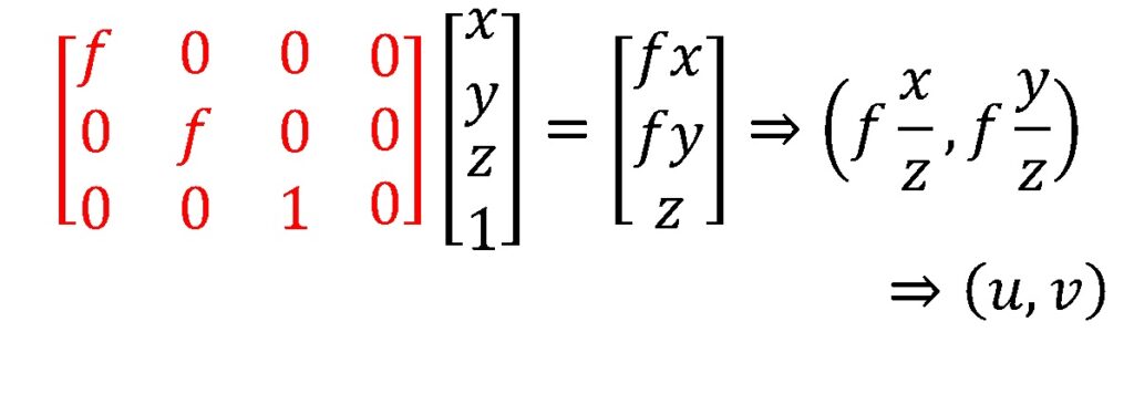
Let’s start with the perspective projection model equations. A very nice thing is that we can write them as a linear matrix operation while we are working in homogenous coordinates. In addition, we do not have to pay much attention to the nonhomogeneous part until the very end. So, here are the equations:

We have a three by four matrix, with values \(1, 1, 1/ f \). We will multiply with it a homogenous 3D coordinate, \begin{bmatrix}x\\y\\z\\1\end{bmatrix}
As a
Our projection operator is a linear matrix multiplication, which is a basis behind projective geometry and projective mathematics.
By the way,\(f \), from now on, is for focal length. Before we’re talking about that distance \(d \), so here our focal length is the distance from the center of projection to the image plane, and it is not the \(f\) of the aperture.
So how does scaling the projection matrix change the transformation? Well, here what we have done is we have scaled our projection matrix by \(f \). We could have scaled it by something else, but we will scale it by \(f \).
So now, instead of having along that diagonal of \(1, 1 \), and \(1 / f \), instead, we just multiply by \(f \) and we have \(f, f \)
Geometric Properties of Projection
All right, let’s just talk quickly about a couple of the geometric properties of perspective projection. What this figure is trying to show
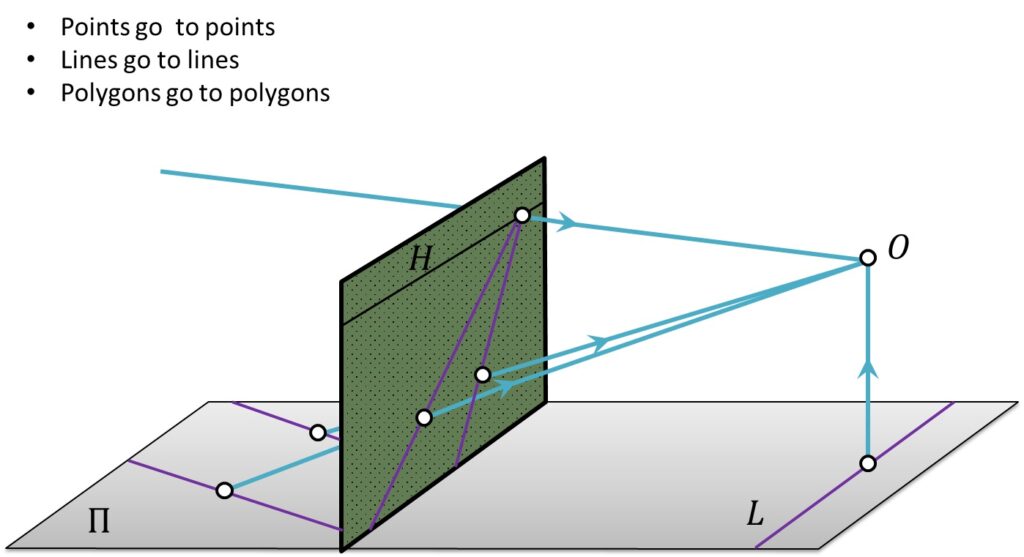
A single point in a 3D world will be positioned in the image plane where a ray intersects an image. This ray passes through the point and the COP (Center of Projection). If we continue to move a point along a line, we realize that it will generate a line in the image plane as well. So, a line will be mapped onto a line in an image plane. Using a similar intuition, we conclude that the polygons will be mapped to polygons.
2. Parallel Lines
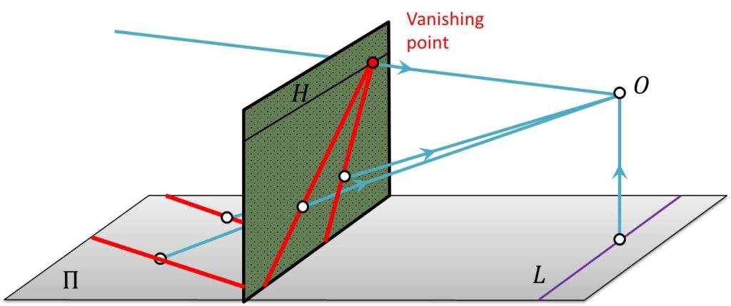
A cool thing in perspective projection that you already know is that parallel lines in the world almost always meet at a point in the image. So here is an example of that, two parallel lines out on the ground plane and they project to two lines in the image. And you can see that they meet at some point, sometimes called the “Vanishing” point in the image.
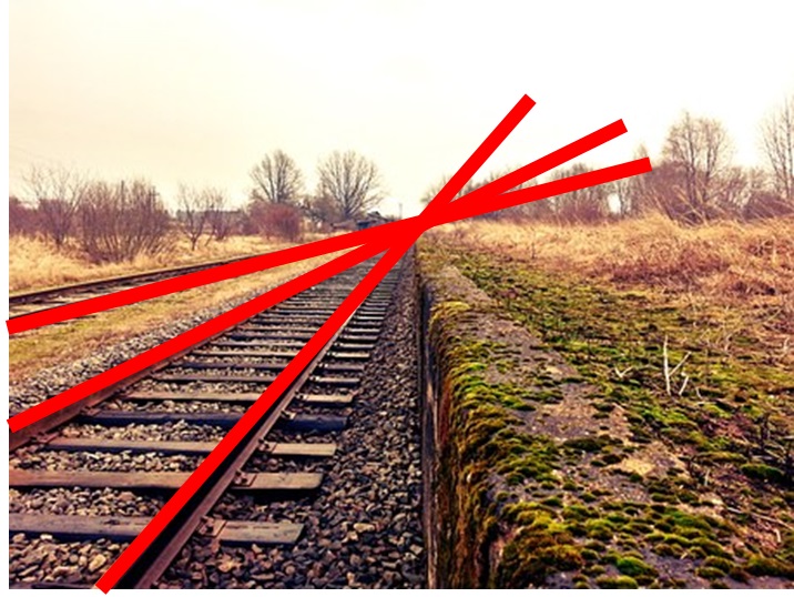
And the canonical example of that is always railroad tracks, where the tracks themselves all converge to a single point.
So we can sort of intuitively think about that. But what is really cool is you can see that directly from the mathematics of it. So let’s think about what a line in a 3D-space is. So, a line in a 3D-space can be parametrized by a single value, a single parameter.
In this case, we are going to use \(t \). Hence, we have \(x\left ( t \right ) \), \(y\left ( t \right ) \) and \(z\left ( t \right ) \), and the idea is as \(t \) changes from maybe minus infinity to infinity or zero to however you want to do it, you would move along that line. And a line in 3-space starts at some point in 3-space. We are saying here, \(x_{0} \), \(y_{0} \), \(z_{0} \). And then it is moved along some vector. So right now, we are using the vector \(a, b, c \). Accordingly, \(a \) in the \(x \) direction, \(b \) in the \(y \) direction and \(c \) in the \(z \) direction, scaled by the value of \(t \).
$$ x\left ( t \right ) = x_{0}+at $$
$$ y\left ( t \right ) = y_{0}+bt $$
$$ z\left ( t \right ) = z_{0}+ct $$
Now, let’s take a look at where all the points on the line lie in the image plane. What is the \({x}’ \) and \({y}’ \) for the given \(t \) for every \(x, y, z\)? Well, we learned that the equation of the projection from \(x, y, z \) to \({x}’ \) is just \(\frac{fx}{z} \) and for \(y \), it is just \(\frac{fy}{z} \). So here, we just substitute it in the expressions from the other side in terms of \(t \).
$$ {x}’\left ( t \right )= \frac{fx}{z}= \frac{f\left ( x_{_{0}}+at \right )}{z_{0}+ct} $$
$$ {y}’\left ( t \right )= \frac{fy}{z}= \frac{f\left ( y_{_{0}}+at \right )}{z_{0}+ct}$$
That is where all the points on the line go, but what happens as \(t \) gets really big? In the limit as \(t\rightarrow \pm \infty \) and we are going to assume for now that \(c\neq 0 \). The limit of \({x}’\left ( t \right )\rightarrow \frac{fa}{c} \). The limit of \({y}’\left ( t \right )\rightarrow \frac{fb}{c} \). But what we are missing is \(x_{0} \), \(y_{0} \), \(z_{0} \). In other words, it doesn’t matter which point in the world this line starts from. As long as the points are all moving in the direction to \(a, b, c \), they are all going to converge at this point in the image.
And that is why it is the case that all parallel lines in the world will all converge to a single point. So the railroad tracks and all parallel lines to a railroad track will converge to the same point.
So what does it mean that \(c \) is zero? When \(c \) is zero means that the \(z \) value doesn’t change. So when our image plane is a vertical plane, that \(z \) is perpendicular. If the \(z \) value doesn’t change, it means the line in the world is parallel to our image plane. Doesn’t get further away or closer, it stays parallel and those lines will all stay parallel lines. And that’s why we said that almost all pairs of parallel lines in the world converge to a point. If you have parallel lines that are vertical or aligned with the image plane, they don’t converge.
3. Vanishing Points
In the following picture the points where these lines meet are called vanishing points. Here is it demonstrated that each set of parallel lines, that means they are all in the same direction, meet at the different point. Another thing that is true is that parallel lines that are all on the same plane, they all converge to colinear Vanishing points. And you know this as the horizon.
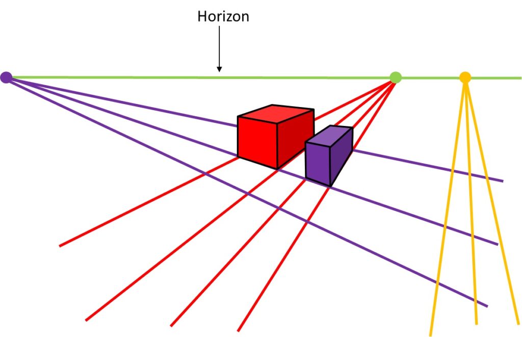
So here is one set of parallel lines in the world. And they converge to a point on the horizon. There is another set of parallel lines. And they also converge to a point on the horizon. If we had parallel lines going away from the camera, they would converge on the horizon. And the horizon is this green line. And that is because all of those parallel lines that we drew, they were all in ground plane, so they all converge at vanishing points on the horizon. By the way it turns out getting the vanishing points consistent, when you are putting together an image is actually kind of hard.
You can often find pictures where the vanishing points don’t seem to do the right thing, and that is because it was made up of parts of an image that weren’t taken with a camera aligned with those parallel lines all in the same way. A little bit more, maybe some of you actually took an art class, before you decided to lose your soul and become an engineer. And maybe they taught you about 3-point perspective. Well and here is a drawing of 3-point perspective.
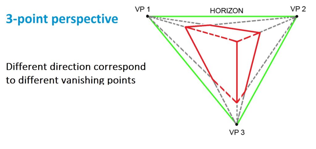
And basically what they are talking about is if we’ve got a cube in the air. That defines three sets of parallel lines. Like the left face, the right face and then underneath. And you could see that drawn here and that is where it comes from, is that parallel lines converge to different Vanishing Points. Here is another example.
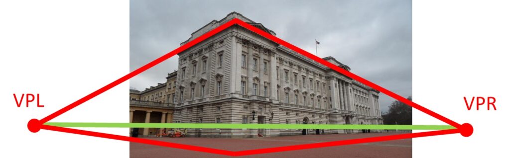
This is a Buckingham Palace. And there is Vanishing point from the right, from the power lines there, another Vanishing point on the left. And without talking about others, you can see where the horizon is, okay, that is this green line, that’s where all the lines for example, on the ground would converge.
Summary
To sum up, in this post we have learned about the Perspective Projection model, and how parallel lines behave differently in the real-world and in perspective projection. We also introduce one new concept, which is Vanishing point. In the next post, we will talk more about human vision and Weak Perspective.